QuadBee - Defend Your Country!
Slava Ukraini! All funds gained from donations and affiliate commission will be going to Ukraine.
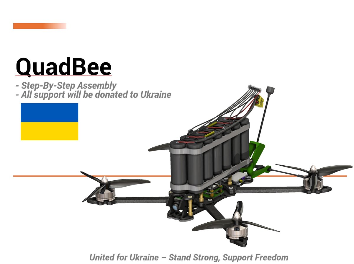
🇺🇦 QuadBee — defend your country
QuadBee is an open-source 7" 6S ExpressLRS FPV quad built around the Mark 4 frame, SpeedyBee F405 V3 stack, and EMAX ECO II 2807 motors. Print it, build it, fly it — or donate, and I'll build one for Ukraine.
Any and all hardware and drones assembled from donations to this project are sent to Ukraine after they're built and tested.

After the Ukrainian army successfully deployed thousands of drones in the field, I wanted to enable regular people to learn, build, and prepare. Homemade drones are effective, and 3D printers have been absolutely crucial — both in the field and for educational use. The goal of QuadBee is to make it realistic for any maker to build their own drone: for fun, for the FPV experience, or as the starting point for something more serious — defensive, reconnaissance, or humanitarian.
📦 Resources
💛 How to support
If you'd like to help fund new components and new designs, any amount goes a long way:
All donations and affiliate commission go directly into hardware for Ukraine.

🖨 Print settings
These are the settings that have given the best success on field-grade parts:
- Material: PC-CF, PA-CF, ASA, ABS, PCTG or PETG (TPU for the antenna brackets)
- Layer height: 0.2 mm
- Wall count: 4
- Solid top/bottom layers: 5
- Infill: 35%
- Infill pattern: Gyroid, Honeycomb, Triangle or Cubic
- Extrusion width: 0.4 mm
TODO: confirm typical print time and part weight for the standard 7" frame.
🛠 Tools you'll need
There's a fair amount of soldering and heat-insert work in this build — if you're new to either, see
🔧 Build notes
A few things worth knowing before you order parts:
- Frame size. The standard build is the 7" Mark 4. There's also a 5" arm variant in the BOM for tighter, more agile builds.
- Battery choice. LiPo 6S 7000–10000 mAh gives the best punch for FPV/freestyle. Li-Ion 6S2P is the right call if you're optimising for long-range or surveillance flights.
- Payload. A redesigned payload system is in progress. The payload units currently linked in the BOM are interim options that work today.
- ELRS region. Build uses 915 MHz ExpressLRS. Match your transmitter module to the receiver region you order — don't mix 868 / 915 / 2.4 GHz.
⚡ Wiring Diagram
Every connection on this build routes through the SpeedyBee F405 V3 stack, which integrates the PDB (power distribution board), ESC (electronic speed controller), and flight controller into a single stackable unit. The BLS 50A BLHeli_32 ESC handles 6S input natively.
Power Distribution
| Connection | From | To | Notes |
|---|---|---|---|
| Battery + (XT60) | LiPo/Li-Ion 6S | PDB BAT+ pad | Solder XT60 directly to PDB power input |
| Battery - (XT60) | LiPo/Li-Ion 6S | PDB BAT- pad | Use 12AWG wire for main power leads |
| Motor 1 | ESC OUT1 | EMAX ECO II 2807 (Front Right) | Any two bell wires swaps rotation |
| Motor 2 | ESC OUT2 | EMAX ECO II 2807 (Rear Left) | |
| Motor 3 | ESC OUT3 | EMAX ECO II 2807 (Rear Right) | |
| Motor 4 | ESC OUT4 | EMAX ECO II 2807 (Front Left) |
Flight Controller Connections
The SpeedyBee F405 V3 FC exposes the following ports for peripherals:
| Peripheral | Signal | FC Pin | Wire Gauge | Notes |
|---|---|---|---|---|
| ELRS Nano RX | UART TX | USART3_TX (Pin D7 / PD7) | 22AWG solid core | Configure Serial RX on UART3 in Betaflight |
| ELRS Nano +5V | Power | FC 5V pad | 22AWG | Regulated 5V from FC BEC |
| ELRS Nano GND | Ground | FC GND pad | 22AWG | Common ground required |
| VTX SmartAudio | Control | SmartAudio pin (Pin B8 / PB8) | 22AWG | For channel/power switching via Betaflight |
| VTX Power | Power | PDB 5V or 9V pad | 18AWG | AKK Race Ranger accepts 5-9V input |
| VTX GND | Ground | FC/PDB GND | 22AWG | |
| Camera Video | Analog Video | FC VIDEO_IN (Pin A7 / PA7) | 22AWG shielded | Caddx Ratel 2 analog output |
| Camera Power | Power | PDB 5V pad | 22AWG | |
| Camera GND | Ground | FC/PDB GND | 22AWG | |
| GPS TX | UART RX | USART6_RX (Pin A3 / PA3) | 22AWG solid core | Configure Serial GPS on UART6 in Betaflight |
| GPS RX | UART TX | USART6_TX (Pin A2 / PA2) | 22AWG solid core | BN-220 telemetry output |
| GPS Power | Power | FC 5V pad | 22AWG | |
| GPS GND | Ground | FC GND pad | 22AWG | Common ground required |
Antenna Connections
| Antenna | Connector | Mount Location | Notes |
|---|---|---|---|
| ELRS Nano RX antenna | SMA (on receiver) | Top plate, rear corner | Point perpendicular to VTX antenna for best diversity |
| VTX antenna | SMA (on AKK Race Ranger) | Top plate, opposite corner from RX | Use the included FPV antenna SMA 10cm or a patch antenna for range |
Antenna placement tip: Mount the ELRS receive antenna and VTX transmit antenna on opposite sides of the top plate with their polarization axes perpendicular (one vertical, one horizontal). This cross-polarization improves link reliability in multipath environments.
Wiring Best Practices
- Use ferrules on all 22AWG signal wire ends before inserting into FC JST-SH or pin headers
- Apply heat shrink over every solder joint — exposed connections cause short circuits under vibration
- Route motor bell wires through the arm channels of the Mark 4 frame to protect them from prop strike
- Use velcro cable ties for all bundling — never zip ties, which are difficult to remove and can damage carbon fiber edges
- Keep power and signal wires separated by at least 20 mm where they run parallel to reduce EMI interference
🔨 Assembly Steps
Follow these steps in order. Complete each step fully before moving to the next.
Phase 1: Frame Preparation
Step 1 — Inspect all frame parts. Unpack the Mark 4 7" frame and verify you have: center plate, four arms (each with integrated motor mount), top plate, and all included hardware. Check each arm for straightness — bent arms cause vibration and handling issues.
Step 2 — Install heat inserts into 3D-printed parts. If you are printing the frame instead of using carbon fiber arms, insert M3 brass heat inserts into every threaded hole using a soldering iron set to 350°C. Press each insert straight until flush with the surface. Let cool for 10 seconds before applying torque.
Step 3 — Attach arms to center plate. Align each arm with the center plate mounting holes. Insert M3 standoffs through the center plate, then secure each arm with M3 countersunk screws. Torque to 0.5 Nm — overtightening cracks carbon fiber or strips printed threads. The Mark 4 uses a standard X-configuration: arms at approximately 45° angles from the forward axis.
Phase 2: Motor Installation
Step 4 — Mount motors to arms. Each EMAX ECO II 2807 motor has four M3 mounting holes matching the arm motor pads. Secure each motor with M3 screws and nylon lock washers. Torque to 0.5 Nm. Verify all four motors sit level with the arm top surface.
Step 5 — Identify motor rotation direction. The EMAX ECO II 2807 6S 1300KV motors are not pre-marked CW/CCW. You will determine correct rotation during Betaflight configuration (see Testing section). For now, note which motor is in each position:
| Position | Motor | Expected Rotation (top view) |
|---|---|---|
| Front Right (M1) | CCW | Counter-clockwise |
| Rear Left (M2) | CW | Clockwise |
| Rear Right (M3) | CCW | Counter-clockwise |
| Front Left (M4) | CW | Clockwise |
Step 6 — Route motor bell wires. Feed each motor's three bell wires through the arm channels toward the center PDB. Leave approximately 150 mm of wire at the ESC end for soldering. Secure wires inside the arms with small velcro ties so they cannot rattle loose during flight.
Phase 3: ESC/PDB Stack Assembly
Step 7 — Assemble the SpeedyBee stack. The SpeedyBee F405 V3 stack consists of three plates that bolt together:
- Bottom plate: PDB with BLS 50A ESC pads (motor outputs, battery input)
- Middle plate: FC mounting layer with vibration dampening silicone pads
- Top plate: Flight controller board
Stack the plates in order. Insert M3 standoffs through all three layers and secure with M3 screws. Use the included silicone damping balls or pads between the PDB and FC to isolate vibration — this is critical for clean IMU readings.
Step 8 — Solder motor bell wires to ESC pads. On the bottom of the PDB, you will find four sets of three solder pads labeled OUT1 through OUT4. Solder each motor's three bell wires to its corresponding output:
- OUT1 → Front Right motor (any wire order)
- OUT2 → Rear Left motor
- OUT3 → Rear Right motor
- OUT4 → Front Left motor
Strip 3 mm of insulation from each bell wire end, tin with solder, then press onto the pad and heat. Apply heat shrink over each joint immediately after soldering. If any motor spins in the wrong direction during testing, swap any two wires on that motor's ESC output — you do not need to desolder; simply pull two wires free and cross them.
Step 9 — Solder battery leads to PDB. Strip 5 mm from each end of the XT60 connector leads. Solder the red (positive) lead to the BAT+ pad and the black (negative) lead to the BAT- pad on the PDB. These pads handle up to 50A continuous — use generous solder for a solid mechanical connection. Cover both joints with heat shrink rated for at least 200°C.
Phase 4: Flight Controller Peripherals
Step 10 — Install ELRS Nano receiver. Mount the ExpressLRS Nano 915 MHz receiver on the top plate using double-sided foam tape. Position it near a rear corner of the top plate, away from the VTX antenna. Solder three wires to the receiver's FC-side pins:
- RX pin → USART3_TX on FC (22AWG)
- +5V pin → 5V pad on FC (22AWG)
- GND pin → GND pad on FC (22AWG)
Screw the included SMA antenna onto the receiver's RP-SMA port hand-tight, then give a gentle quarter-turn with finger pressure — do not use tools on the SMA thread. Route the three signal wires along the edge of the top plate and secure with velcro ties.
Step 11 — Install AKK Race Ranger VTX. Mount the VTX on the top plate near the front or side, as far from the ELRS receiver antenna as possible. Connect:
- SmartAudio pin → SmartAudio pad on FC (22AWG)
- Power (+) → PDB 5V or 9V pad (18AWG recommended for VTX current draw)
- Ground (-) → GND pad (22AWG)
Screw the FPV antenna onto the VTX's SMA port. The AKK Race Ranger outputs up to 1.6W — ensure your antenna is rated for this power level. Route the video cable from the camera to the VTX video input (if using a standalone VTX with video passthrough; the AKK Race Ranger typically connects directly to the camera output).
Step 12 — Install Caddx Ratel 2 camera. Mount the camera on the front of the frame facing forward. The Caddx Ratel 2 uses a standard FPV camera mount pattern. Connect:
- Video out → FC VIDEO_IN pin (use shielded cable, 22AWG)
- Power (+) → PDB 5V pad (22AWG)
- Ground (-) → GND pad (22AWG)
Route the video cable along the top plate edge toward the VTX. If the camera has adjustable focus, set it now: power the battery, view the feed through your goggles, and adjust the focus ring until the image is sharp at flying distance.
Step 13 — Install Beitian BN-220 GPS module. Mount the GPS on top of the top plate using double-sided foam tape or a dedicated GPS mount. The BN-220 has an integrated ceramic patch antenna that must face unobstructed sky — never mount it under metal or carbon fiber thicker than 3 mm. Connect:
- TX pin → USART6_RX on FC (22AWG)
- RX pin → USART6_TX on FC (22AWG)
- VCC (+5V) → 5V pad on FC (22AWG)
- GND → GND pad on FC (22AWG)
The integrated buzzer provides audible satellite lock feedback. Position the GPS so the buzzer faces outward for audibility during pre-flight checks.
Phase 5: Final Assembly
Step 14 — Install battery mount. Attach the battery strap or mounting system to the center plate or bottom of the frame. The 6S 7000-10000mAh battery is heavy (approximately 600-900g) — ensure the mount can handle this weight securely. Position the battery so the center of gravity sits near the geometric center of the frame, slightly behind the FC for optimal pitch response.
Step 15 — Cable management and final inspection. Run through this checklist:
- All solder joints have heat shrink applied
- All wires are secured with velcro ties — no loose cables that could flap in airflow
- Motor bell wires are routed inside arm channels, not exposed on the outside
- Antennas are screwed on and pointing outward (not tucked under plates)
- All M3 screws are torqued to 0.5 Nm
- No tools or loose hardware remain on the frame
💻 Firmware Configuration
Flashing Betaflight
- Download Betaflight Configurator (latest stable release, v11.x or newer).
- Connect the SpeedyBee F405 V3 to your computer via USB-C cable. Hold the button on the FC while plugging in to enter DFU bootloader mode — the LED will blink rapidly.
- Open Betaflight Configurator and click Connect with the CLI tab open. Select port speed 115200.
- Go to the Configuration tab and verify the board is detected as
SPEEDYBEEF405V3or similar SpeedyBee F405 target. - Go to the CLI tab and run:
set board_name=SPEEDYBEEF405V3 set serialrx_provider=ExpressLRS save - Alternatively, use the Flasher tab to flash the latest stable Betaflight release for the SpeedyBee F405 V3 target.
Port Configuration
Navigate to the Ports tab in Betaflight Configurator:
| UART | Function | Setting |
|---|---|---|
| UART1 | Telemetry (optional) | Enable if using GPS telemetry passthrough |
| UART2 | OSD (if separate) | Usually not needed — SpeedyBee has integrated OSD |
| UART3 | ExpressLRS Receiver | Enable Serial RX |
| UART4 | Unused | Disable |
| UART5 | Unused | Disable |
| UART6 | GPS (BN-220) | Enable GPS |
Receiver Setup — ExpressLRS Binding
- Install the RadioMaster Bandit Micro ELRS 915 MHz module into your TX12 Mark II radio.
- Power on the transmitter and navigate to Model Setup → Model Specific → Internal Module → Protocol. Select ExpressLRS.
- On the drone, connect battery (props removed). The ELRS Nano LED will blink — it is in binding mode for approximately 10 seconds after power-on if no prior bind exists.
- On the transmitter, go to Model Setup → Model Specific → Internal Module → Bind and press the bind button. The ELRS Nano LED on the drone should turn solid green within 5 seconds.
- Verify in Betaflight Configurator under the Receiver tab: move sticks on your TX12 and confirm channels AIL, ELE, THR, RUD update in real time.
VTX Setup — SmartAudio
- In Betaflight Configurator, go to the Configuration tab.
- Set Video Transmitter to SmartAudio.
- Go to the OSD tab and verify the VTX status appears (channel, power level).
- The AKK Race Ranger supports 40 channels in the 5.8 GHz band. Use the standard FATSHARK or RACEBAND channel table depending on your goggles compatibility.
- Set maximum VTX power: FCC region = 1.6W (High), CE region = 200mW (Low). Check your local regulations before setting High power.
PID Tuning — 7" 6S Build Recommendations
The EMAX ECO II 2807 1300KV on 6S produces aggressive throttle response. Start with these baseline PID values and tune from there:
Profile 1 — Racing / Aggressive Freestyle:
# Angles / Rates mode: Acro
set roll_rc_rate = 180
set pitch_rc_rate = 180
set yaw_rc_rate = 160
set roll_srate = 75
set pitch_srate = 75

# PIDs (acro mode)
set roll_p = 58
set roll_i = 65
set roll_d = 42
set pitch_p = 55
set pitch_i = 62
set pitch_d = 40
set yaw_p = 95
set yaw_i = 70
set yaw_d = 0

# D-term filtering
set dterm_notch_hz = 100
set dterm_notc_cutoff = 300
set gyro_lowpass2_hz = 150
Profile 2 — Long Range / Surveillance:
# Gentler rates for stable camera work
set roll_rc_rate = 140
set pitch_rc_rate = 140
set yaw_rc_rate = 130
set roll_srate = 60
set pitch_srate = 60

# Softer PIDs
set roll_p = 48
set roll_i = 52
set roll_d = 35
set pitch_p = 45
set pitch_i = 50
set pitch_d = 32
set yaw_p = 80
set yaw_i = 60
set yaw_d = 0

# Throttle curve for smooth cruise
set throttle_midi = 0.55
Tuning note: These are starting points. Use Betaflight's built-in blackbox logging to analyze gyro traces and adjust D-term to eliminate oscillation without over-damping. Increase P until the drone responds crisply, then add I to eliminate drift. Add D only as much as needed to stop overshoot.
GPS Mode Setup — Return to Home
- In Betaflight Configurator, go to the Modes tab.
- Enable GPS Rescue (RTH) on a switch channel or as a failsafe action.
- Go to the CLI and configure:
set gps_rescue_velocity = 2000 set gps_rescue_altitude = 50 set gps_rescue_descent_altitude = 20 set gps_rescue_throttle = 1800 set gps_rescue_angle = 20 save - This configures RTH to climb to 50 m, fly home at 2000 mm/s, then descend at 20 m altitude before landing.
🧪 Testing and Calibration
Complete every test with propellers removed until Step 7. Power the drone on a flat, non-metallic surface away from people and obstacles.
Test 1 — Motor Direction Check
- Open Betaflight Configurator → Motors tab.
- Drag each motor slider individually and observe rotation direction from above:
- Front Right (M1): should spin CCW
- Rear Left (M2): should spin CW
- Rear Right (M3): should spin CCW
- Front Left (M4): should spin CW - If any motor spins the wrong way, swap any two bell wires on that motor's ESC output. Do NOT change the motor order in software — fix it physically by swapping wires.
Test 2 — Receiver Signal Verification
- Open Betaflight Configurator → Receiver tab.
- Move each stick on your TX12 and verify all channels respond:
- AIL (Channel 1): Left/Right stick horizontal
- ELE (Channel 2): Left/Right stick vertical
- THR (Channel 3): Right stick vertical
- RUD (Channel 4): Right stick horizontal - Check ELRS RSSI in the OSD — values above 50% at 5 m distance indicate good antenna placement. Below 30%, reposition antennas.
Test 3 — Failsafe Testing
- In Betaflight Configurator → Setup tab, check Failsafe settings:
- Failsafe mode: GPS Rescue (if GPS is installed) or Kill (motors stop immediately)
- Failsafe throttle level: 0 (kill) or configured RTH throttle - Power on the drone and transmitter. After confirming link, turn off the transmitter.
- Observe behavior: motors should either stop immediately (Kill mode) or the drone should initiate RTH after a 3-second delay (GPS Rescue). Do not catch the drone — let it land safely on its own during this test.
Test 4 — GPS Calibration and Satellite Lock
- Take the drone outdoors to an open area with clear sky view.
- In Betaflight Configurator → Setup tab, click Calibrate Accelerometer with the drone level on a flat surface.
- Click GPS Rescue status indicator and wait for satellite lock:
- BN-220 acquires initial fix in 30-90 seconds (cold start)
- Buzzer will emit periodic beeps as satellites are acquired
- Minimum 5 satellites required for GPS Rescue to arm - Verify the OSD shows GPS coordinates and satellite count during flight simulation.
Test 5 — VTX Power and Channel Switching
- Put on your FPV goggles and tune to a known channel (e.g., Race Band channel R1 = 5865 MHz).
- In Betaflight Configurator → OSD tab, verify the VTX shows the correct channel and power level.
- Use SmartAudio voice commands or OSD menu to cycle through channels: confirm you hear the VTX beep and see the goggles switch cleanly on each channel.
- Verify video signal is clear with no excessive noise or snow.
Test 6 — Camera Image Quality
- View the Caddx Ratel 2 feed through your goggles.
- Adjust camera focus ring until text at 5 m distance is legible in the FPV feed.
- Check for image roll-bar (horizontal banding) — if present, adjust the FPV Delay setting in Betaflight OSD configuration until the bar disappears.
Test 7 — Battery Voltage Monitoring
- Connect the battery and check the voltage display in Betaflight Configurator → Status tab.
- A fully charged 6S LiPo reads 25.2V (4.2V per cell). A fully charged 6S Li-Ion reads 25.2V as well, but discharges more gradually.
- Verify the low-voltage warning triggers at approximately 19.8V (3.3V per cell) in the OSD. Adjust
set battery_warning = 3if needed.
⚠️ Safety Warnings
🔋 6S LiPo Battery Handling
- Always use a balance charger with a dedicated LiPo charging mode. Charge at 1C maximum (7A for a 7000mAh pack, 10A for a 10000mAh pack).
- Never leave a charging battery unattended. LiPo batteries can catch fire if overcharged, shorted, or physically damaged.
- Store in a LiPo safety bag or fireproof container during charging and storage.
- Inspect before every flight: check for swelling, punctures, exposed wiring, or burnt connectors. A swollen cell indicates internal damage — dispose of the battery safely at an electronics recycling facility.
- Storage voltage: Store LiPo cells at 3.8V per cell (22.8V total for 6S) if not flying for more than one week. Do not store fully charged or fully discharged.
- Disposal: Never throw LiPo batteries in regular trash. Take them to a battery recycling center with the connector taped off to prevent short circuits.
🌀 Propeller Safety
- Never apply throttle with propellers installed during testing. Remove all four props before connecting to Betaflight Configurator, running motor tests, or checking orientation.
- Keep hands and tools clear of spinning props. 7" props at full throttle on a 6S build generate enough force to break fingers and cause serious lacerations.
- Use threadlocker on prop nuts. Apply blue Loctite (medium strength) to prop nut threads to prevent vibration loosening during flight.
- Inspect props before every flight. Cracked, chipped, or bent props cause vibration, reduce efficiency, and can shatter at speed — sending sharp plastic fragments in all directions.
- Remove props when transporting the drone. Store props separately in a prop bag.
📡 Radio Frequency Regulations
- 915 MHz ISM band (United States): FCC Part 15 compliant operation is permitted without license. Maximum EIRP is limited by device certification — the ExpressLRS Nano operates within legal limits.
- 868 MHz ISM band (Europe): ETSI regulations apply. If operating in the EU, use an 868 MHz ELRS receiver and module instead of 915 MHz. Mixing regions causes no-link conditions.
- VTX power limits: FCC allows up to 1W EIRP for 5.8 GHz FPV video transmitters without special licensing. The AKK Race Ranger's 1.6W output exceeds this — check local regulations. In the EU, VTX output is limited to 200mW (25dBm) under CE rules.
- Always verify local drone regulations before flying. Many countries require registration, pilot licensing, or have altitude/airspace restrictions.
✈️ Flight Safety
- Pre-flight checklist: Run through every test above before your first flight with props installed. Create a printed checklist and use it for every flight session.
- Fly in open areas. Keep minimum 50 m distance from people, structures, roads, and power lines during testing. Increase this distance as you gain confidence.
- Maintain visual line of sight where required by local regulations. FPV goggles give you the pilot's perspective but not situational awareness of surrounding airspace.
- Respect no-fly zones. Stay clear of airports (minimum 5 km / 3 statute miles), military installations, emergency response areas, and populated urban centers unless explicitly authorized.
- Have a spotter for your first flights — someone who maintains visual contact with the drone and can relay position information to you through an earpiece or radio.
🔌 Electronics Safety
- Soldering precautions: Work in a well-ventilated area. Use a fume extractor when soldering. Wear eye protection when using heat inserts — hot brass can eject from the insert tool if over-heated.
- Heat shrink all exposed connections. Uninsulated solder joints on a vibrating drone will eventually short against adjacent traces or metal parts.
- Waterproofing for field use: Apply conformal coating to the FC and ESC boards if flying in rain or high humidity. Use silicone sealant around antenna SMA mounts and cable entry points. The BN-220 GPS is not waterproof — add a clear plastic dome cover if operating in wet conditions.
💻 Firmware
- Flight controller: SpeedyBee F405 V3 stack with BLS 50A ESC, running Betaflight.
- Receiver: ExpressLRS Nano 915 MHz, bound to a RadioMaster Bandit Micro module.
- VTX: AKK Race Ranger 1.6 W (SmartAudio).
🚀 Roadmap
Any design that comes out of this project gets uploaded as a variant and stays open for anyone to use. I rely on donations to actually test designs — there's only so far CAD alone gets you. For obvious reasons I can't share the CAD files currently in use in the field; that's why new designs keep coming.
Short to medium term I want to:
- Develop and share a new payload system (interim payload units are in the BOM)
- Build variants that handle different payload types
- Build a variant for transporting medical supplies, including refrigerated medicine
- Build variants for other purposes — mine detection and similar
- Streamline the enclosures to at least IP2x
Slava Ukraini! 🇺🇦
Bill of materials
| Component | Qty | Source | Buy |
|---|---|---|---|
| Caddx Ratel 2 12000 TVL | 1 | amazon |
Amazon ↗
product
|
| 915 MHz receiver Express LRS Nano | 1 | amazon |
Amazon ↗
product
|
| SpeedyBee F405 V3 Stack BLS 50A | 1 | amazon |
Amazon ↗
product
|
| VTX AKK Race Ranger 1.6W | 1 | amazon |
Amazon ↗
product
|
| EMAX ECOII Series ECO II 2807 6S 1300KV | 4 | amazon |
Amazon ↗
product
|
| FPV antenna SMA 10cm | 1 | amazon |
Amazon ↗
product
|
| HQPROP 7035 7x3.5x3 | 4 | amazon |
Amazon ↗
product
|
| Mark 4 7'’ frame | 1 | amazon |
Amazon ↗
product
|
| XT60 connectors | 2 | amazon |
Amazon ↗
product
|
| RadioMaster Bandit Micro ELRS 915 MHz Radio Adapter | 1 | amazon |
Amazon ↗
product
|
| Beitian BN-220 GPS module and Buzzer | 1 | amazon |
Amazon ↗
product
|
|
LiPo 22.2V 6S Battery (7000-10000mAh)
Li-Po more powerfull discharge / Power output. Better for FPV Racing
|
1 | amazon |
Amazon ↗
product
|
|
Lithium-Ion 22.2V 6s2p Battery (7000-10000mAh)
Li-Ion better for long range flights
|
1 | amazon |
Amazon ↗
product
|
| 5.8G FPV Goggles 40CH X BAND | 1 | amazon |
Amazon ↗
product
|
| RadioMaster TX12 Mark II Radio Controller | 1 | amazon |
Amazon ↗
product
|
|
Alternative Mark 4 5" frame
5 inch arm - Alternative
|
1 | amazon |
Amazon ↗
product
|
|
Drone Payload System
Alternative untill new redesign
|
1 | amazon |
Amazon ↗
product
|
|
Dual Payload System
Alternative untill new redesign
|
1 | amazon |
Amazon ↗
product
|
| Heat insert set | 1 | amazon |
Amazon ↗
product
|
|
Power Wire
12AWG - (For 2A and/or 5v)
|
1 | amazon |
Amazon ↗
product
|
|
Communication / Signal Wire
22AWG - (Recommend solid core)
|
1 | amazon |
Amazon ↗
product
|
| Ferrules Set | 1 | amazon |
Amazon ↗
product
|
| Reusable Velcro Cable Ties | 1 | amazon |
Amazon ↗
product
|
| Heat Shrink | 1 | amazon |
Amazon ↗
product
|
| M3 Countersunk screw set | 1 | amazon |
Amazon ↗
product
|
|
Distances (Standoffs M3)
Needed if you want to 3d-print the frame
|
1 | amazon |
Amazon ↗
product
|
|
Heat insert set
Alternative
|
1 | amazon |
Amazon ↗
product
|
|
M3 Button Cap Set (Alternative)
Alternative link
|
1 | amazon |
Amazon ↗
product
|
|
M3 Socket head cap (Alternative
Alternative link
|
1 | amazon |
Amazon ↗
product
|
|
M3 Heat Insert set (Alternative
Alternative link
|
1 | amazon |
Amazon ↗
product
|
|
M3 Spacers/Distances (Alternative
Alternative link
|
1 | amazon |
Amazon ↗
product
|
| PC / ASA / ABS / PETG Filament | 1 | amazon |
Amazon ↗
product
|
| PC-CF / PETG-CF / PA-CF / ABS+ (Engineering Grade Filaments) | 1 | amazon |
Amazon ↗
product
|
| PLA | 1 | amazon |
Amazon ↗
product
|
| TPU | 1 | amazon |
Amazon ↗
product
|
|
Soldering Iron TS101
(Recommended)
|
1 | amazon |
Amazon ↗
product
|
|
Heat Inset Tip Kit - For TS101
(Recommended)
|
1 | amazon |
Amazon ↗
product
|
|
Electric Precision Screwdriver
(Recommended)
|
1 | amazon |
Amazon ↗
product
|
|
Allen Key Set
(Recommended)
|
1 | amazon |
Amazon ↗
product
|
|
Torx Key Set
(Recommended)
|
1 | amazon |
Amazon ↗
product
|
|
Torque Screwdriver
(Recommended)
|
1 | amazon |
Amazon ↗
product
|
|
Wire stripper
(Recommended)
|
1 | amazon |
Amazon ↗
product
|
|
Wire cutter
(Recommended)
|
1 | amazon |
Amazon ↗
product
|
|
Heat Insert Press Tool
(Recommended)
|
1 | amazon |
Amazon ↗
product
|
|
Crimp Tool
(Recommended)
|
1 | amazon |
Amazon ↗
product
|
|
Soldering Iron - Generic (Alternative)
Budget friendly alternative
|
1 | amazon |
Amazon ↗
product
|
|
Heat insert tip - set (Alternative)
Budget friendly alternative
|
1 | amazon |
Amazon ↗
product
|
|
Precision Screwdriver Set
Budget friendly alternative
|
1 | amazon |
Amazon ↗
product
|